make an in-circuit programmer by milling and stuffing the PCB, test it, then optionally try other PCB processes
I will print the electronic board using Roland SRM-20
Roland SRM-20 is a machine for making electronic boards, by drilling tracks on the surface of a board, and by cutting a board

These Milling Bit are used for cutting and drilling
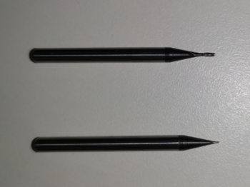
This image is for milling traces

This picture is for the outside cut

The first thing we take these pictures to is the Fab Modules website to create an rml file

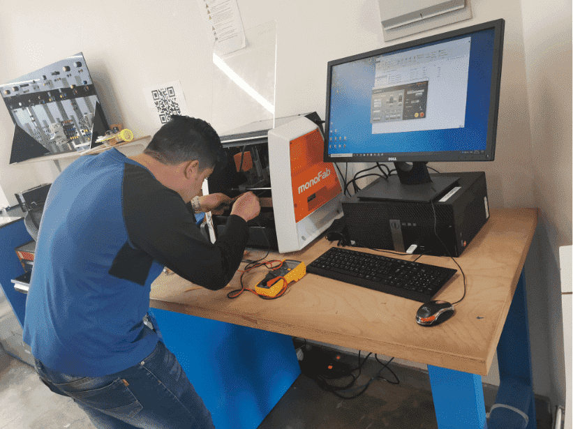
After that, we place the electronic board inside the Roland SRM-20 and using the double-sided patch we install the board inside the machine.

Using the control panel, we zero the machine on the surface to be painted

Using two rml files (cut and drill), we put them inside the machine program to print them, then we press the cut command from the control panel to start cutting
Before that, we make sure that the vane is connected to the board surface using an avometer
When we finish cutting and drilling, we vacuum the fridge from the machine

I had a problem accidentally changing my dpi to 599.99 but I set it to 1000.2
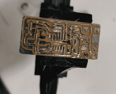
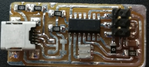
this is the final shape of the electronic board after cutting and drilling the tracks

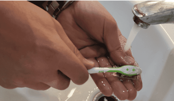
Then we take the cut piece and then wash it under water and using a brush
Next we start soldering by filling a layer of tin on the surface of the tracks, and then wiping it with tape and flux.
After that we start soldering and installing the pieces. Note: when installing the pieces all of them should be in its proper place and direction
These are the parts used:
-
Attiny 44 microcontrolar (1)
Capacitor 1uf (1)
Resistor 100 ohm (2)
Resistor 499 ohm (1)
Resistor 1k ohm (1)
Resistor 10k ohm (1)
6pin header (1)
USB connector (1)
jumpers -0 ohm (1)
cystal 20 MHZ (1)
Zener diod 3.3v (2)
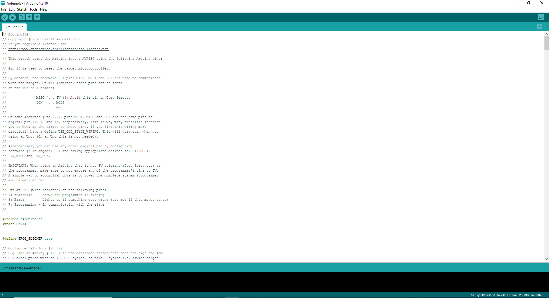
To start programming, we need an Arduino board and connectors to program the board, and we will need the Ubuntu system
Through the Arduino board we will put the board that we made into DNA like mind so that the board knows how to program
We will need to set the Arduino program on ISP Arduino, on the Attiny family. After that we click from the Tools menu on the burn the bootloader.
After that we install the Ubuntu system and update the library in order not to have problems, then we run the system.
From the list of programs, we open a program called terminal to start entering the codes for electronic board programming
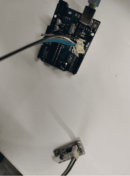
We will connect the Arduino board to the board we made. And connect it with the computer
There are several commands that must be followed to program the board: First of all, we install the necessary package to program AVR 1 We install the following commands to activate the AVR library on the computer:
sudo apt-get install flex byacc bison gcc libusb-dev avrdude
sudo apt-get install gcc-avr
sudo apt-get install avr-libc
sudo apt-get install libc6-dev
2-We download and install the DNA or the mind of the device using these commands: First we define the destination, for example the desktop, after that we write a command (wget http://academy.cba.mit.edu/classes/embedded_programming/firmware.zip) Then we extract the files where we want them.
3- We install the DNA of the board using these instructions:
sudo make clean: to delete files that are not compatible with ATTINY44
sudo make hex: to create files that match the board Then we add a hashtag "#" note before the written line and add a note after it
Then we use the sudo make fuse command to link the file to be executed
sudo make program: This command collects the board with the file.
This is aTXT file for all of your steps

Then we try the board: put the USB connection to the board and write the lsusb command: to test the board and print the word (Multiple Vendors USB Tiny) the board is programmed correctly
I will drill the traces using the vinyl cutter First I will open the CorelDraw program and put the image inside the program and draw a square on the photo frame and use the (Quick Trace) command from the Trace Bitmap Tools menu, then we color the shear lines with the color of the cut, so the image to be cut is like the one below

After that, we save the image in (pdf) format for cutting it on vinyl cutter using Versa Works

By clicking two files on the file to adjust the settings for the cutting using a vinyl cutter machine, as shown in the picture

After agreeing to the approval, we start printing on the vinyl cutter

After many attempts on the vinyl cutter I used more than one cut option that I did not succeed with, and the result was like this.

This is the site for group assignments:Press here
group assignment:
characterize the design rules for your PCB production process
This link contains documentation for group work.